


3 Phase Voltage Indicator / Live Line Indicator

$709.50 incl. GST
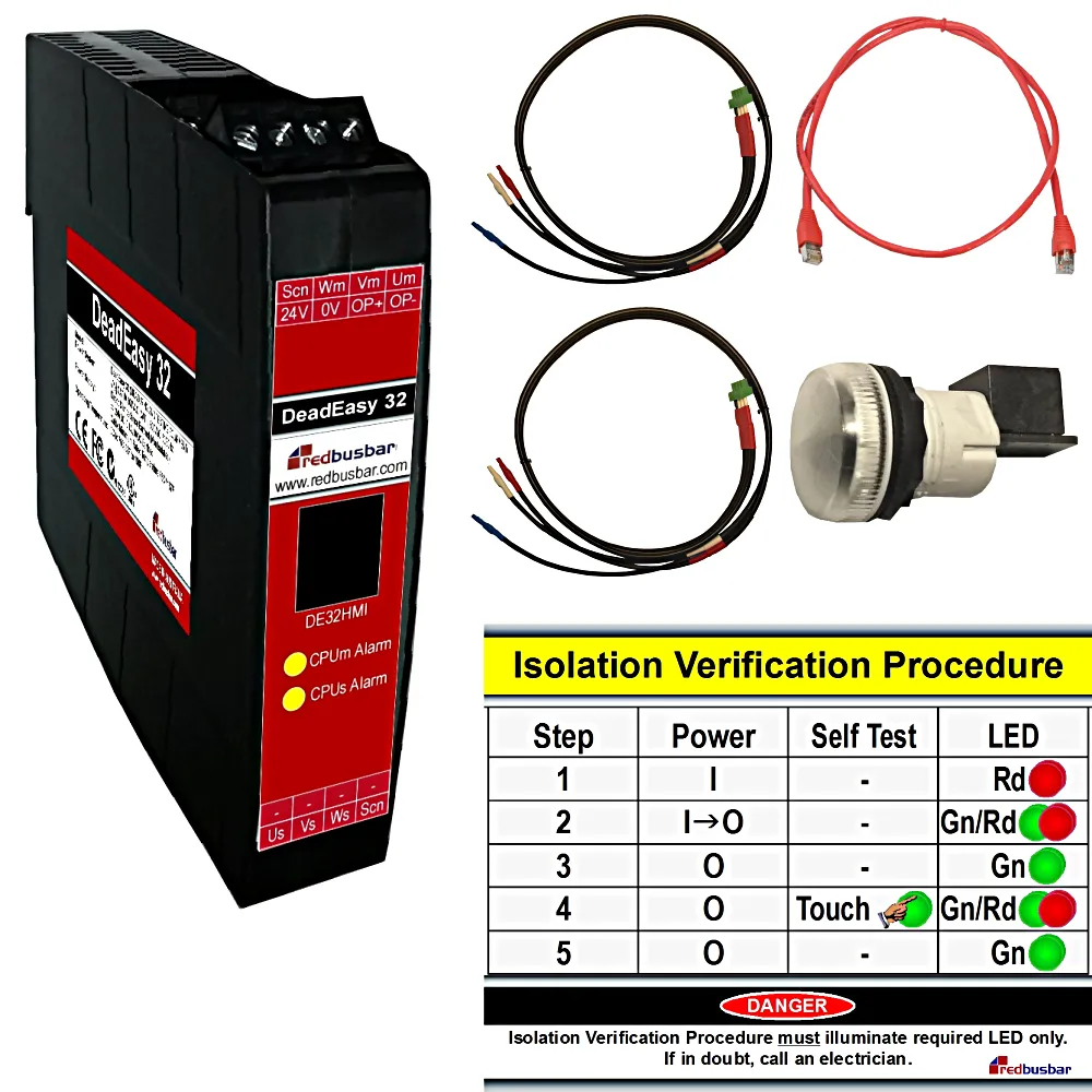
Electrical Isolation Confirmation / Isolation Verification, Test for Dead Test Device – Kit for 1 Isolation Switch Including One DeadEasy (DE32), One DeadEasy Human Machine Interface (DE32HMI), One DeadEasy Human Machine Interface cable (DE32HMIC), Two DeadEasy Instrument cables (DE32IC) for 1 Isolation Switch
DeadEasy is a 3 phase, switchboard mounted, voltage indicator that incorporates functional safety design. It is used to verify that an electrical isolation switch is open, as part of a lockout procedure.
DeadEasy three phase indicator tests an electrical circuit by sensing the existence or absence of an electric field surrounding the electrical phase conductors. In essence, DeadEasy is a permanently installed, non-contact, three phase live line indicator.
DeadEasy Operation Video
DeadEasy Features Video
Features
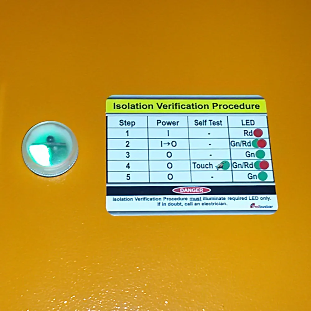
Positive Indication on Deenergisation
The green LED is illuminated when the circuit is dead / deenergised. This rules out the question – Did the lamp fail as I turned the switch off or is the led indicating that the power is really off?
Self Test Function
Self Testing is performed automatically:
- On DeadEasy 24VDC power up, and
- Every alive to dead power circuit (red to green LED) transition, and
- Periodically during dead power circuit (green LED) indication.
This automatic testing is in addition to the manual testing capabilities available while the green LED is illuminated. Every self test performs a sequence of tests as follows:
- The master channel generates a test voltage which the slave channel is expects to detect
- The master channel removes the test voltage which the slave channel is expects not to detect
- The slave channel generates a test voltage which the master channel is expects to detect
- The slave channel generates a test voltage which the master channel is expects not to detect
This 2 second test sequence results in red and green LED flashing. The self test confirms the correct function of the sensing conductors, logic processing unit, output LEDs and all interconnecting wiring is confirmed. A true safety rated self test!
Non-contact Sensing
DeadEasy sensing conductors do not electrically connect to the power circuit under test. The insulated sensing conductors are wrapped around the insulated power conductors during installation. This approach removes the need for voltage indicator, short circuit protection devices on the power circuit. In addition it eradicates the risk of the mains indicator introducing a weak point into your power system. A weak link than can fail catastrophically during power system voltage surges. Just ask yourself – Why introduce a safety device that potentially introduces a new safety risk?
Digital Output
Active on green LED. Allows you to log the deenergised event and/or enables field indication of the deenergised equipment, at the equipment. Now you can match switchboard isolations with field equipment!
Other Benefits
- Allows non-electricians to perform a “Test for Dead” / “Zero Voltage Verification” style test on an electrical circuit.
- Is simple to use.
- Is an inexpensive alternative to manual testing methods such as Dead Test, Try Start
- Is simple to install. 25mm wide DIN rail mount electronics, HMI incorporating power indicator leds and self test request all in one only 22.5mm panel lamp cut-out.
- Has wide application. DeadEasy is suitable for new and retrofit installations and dusty, low and high ambient light environments.
- Is flexible. DeadEasy, live line indicator allows subsequent verifications without reversal of the isolation ie accommodates late working parties.
- Replaces traditional three single phase led / neon mains indicators.
- Reduces exposure to arc flash / faults. The energised state of phase conductors is known before panel doors are opened to conduct tests.
- Is reliable. Hand held, non-contact, voltage indicator leds depend on a user’s unreliable connection to earth potential. DeadEasy’s reference to earth is via a permanent wired connection.
DeadEasy Background
DeadEasy tests an AC circuit to establish whether the circuit is both energised and de-energised (alive and dead). DeadEasy uses Super Bright LEDs so the test result is clear and obvious. DeadEasy provides non-electrical people with a simple and safe zero voltage verification method for MCC / Switchboard based, electrical isolations before conducting mechanical maintenance. In addition, confirmation of the de-energised state of the ac phase conductors inside a cabinet reduces the need to open the cabinet to test for dead and hence expose personnel to a potential Arc Flash / Fault. Confirmation of the de-energised state of the circuit inside the cabinet may reduce the level of Arc Flash PPE required to open the cabinet door.
It is simple and fast to use. No licenses are necessary. Anyone can operate DeadEasy, power indicator light.
DeadEasy’s non-contact, testing approach is used extensively in medium and high voltage applications, DeadEasy’s focus is low voltage (< 1000V / 1kV AC) systems. DeadEasy is switchboard / MCC mounted so that one DeadEasy phase indicator is dedicated to one circuit. It is ideally suited to installation within a motor control centre on controlled circuits. Specifically, on the short length, circuit conductors between the isolating device ( switch or circuit breaker ) and the controlling device ( contactor, soft starter or variable speed drive ).
Package Includes
- DeadEasy DIN Rail Mounted Electronics (DE32)
- DeadEasy Human Machine Interface and Procedure Label (DE32HMI)
- DeadEasy Human Machine Interface cable (DE32HMIC)
- 2 off DeadEasy Instrument cables (DE32IC)
- Installation and operation manual
FAQ
Mainly because electrical isolations, even if the correct switch is turned off and locked, are not always sound.
We generally think that once we have turned off and locked an isolating switch or circuit breaker that the equipment is 100% safe to access. Not so, many, many switches from the largest manufacturers have failed in a mode that allows switches to pass current in the “off” position. The switch failures have caused fatalities in Australia and in the USA. The fatalities have motivated legislators towards the need to verify isolations. This legislation now requires isolation confirmation or verification of isolation. Many tests have been developed to test isolating switches. Some tests that are used today are cumbersome and some are potentially misleading.
Switch failure modes that allow the passing of current in the off position include:
- Welded switch contacts.
- Worn handles that fail to rotate the switch mechanism when the handle is rotated.
- Misaligned handles that fail to engage with the “handle to switch” connecting shaft.
- Switch bypass faults – cable-to-cable faults.
Perhaps there is a message in the fact that all major manufacturer’s of isolating switches now incorporate Visible Break Isolators (VBI) in their range!
DeadEasy 3 phase indicator was designed to:
- Provide non-electrical people with a simple and safe method of verifying MCC (Motor Control Centre) based, electrical isolations before conducting mechanical maintenance.
- Provide operator confidence in the reported test result through the use of a operator initiated, self test function.
- Be implemented in new and retrofit applications by being inexpensive to purchase and simple to install.
- Provide minimal impact on the integrity of the power system to which it is connected.
Test for Dead / Live-Dead-Live check is the undisputed, and normally mandated, approach to confirm that an isolation has been verified prior to performing electrical maintenance. So we started thinking “How can we provide a tool that a non-electrician could use to perform a Test for Dead / Live-Dead-Live check?”. We recognised that the integrity of the test result came from the rigid test sequence and its simplicity rather than any sophisticated instrument. So our approach was to use LEDs to indicate presence and absence of voltage combined with a rigid but simple test procedure. In this way it is strikingly similar to a Test for Dead / Live-Dead-Live check.
SwitChek isolation switch tester provides greater testing flexibility than DeadEasy LED phase indicator as it can conduct a test whether or not the line side of the switch is alive or dead. This is important for field isolators as the line side of the switch is most likely to be deenergised at the time of testing. DeadEasy requires the line side of the switch to be alive at the time of testing. As such, it is most suitable for switchboard or motor control centre verification of isolation.
The direct contact measurement approach introduces the following:
- A weak point in the power system in terms of overvoltage withstand capability.
- The need to have different installation approaches to connect to different size mains cables.
- The risk of an insulation fault on the sensor leads causing an arc flash that is only protected by the upstream power system protection. The potential for significant damage/personnel harm.
- The need to segregate the sensor leads from other control system cables to minimise electrical noise and if segregation is not performed, the risk to someone tracing control system conductors in ducts and raceways using their hands and receiving an electrical shock.
- The need to keep sensor leads short to minimise the risk of a sensor lead fault. This means that the logic module needs to be located close to the power conductors. In a segregated MCC this means that the logic module is located in the cable way which is inaccessible for fault finding purposes.
DeadEasy three phase indicator measures the electric field that is generated by a live AC phase conductor. All live AC conductors generate this field. When the source generating the field is referenced to earth eg via an neutral to earth link, the field also seeks a path to earth through DeadEasy. Other devices that use this principle to determine whether a conductor is live or dead include non-contact test pencils and high voltage, live line indicators.
Non-contact test pencils have not always had a good reputation. This seems to be due to the poor integrity of the earth connection provided by the operator. That is, PPE such as gloves and work boots may impede the operator’s path to earth and prevent the detection of a live conductor. Where the connection to earth is sound, the approach is regarded as safe and as such forms the basis of most high voltage test for dead, live dead live, testing. This technique is enhanced if self testing is employed as in the case of DeadEasy.
One problem that may exist with non contact capacitive methods is the reporting of deenergised conductors as energised. Whilst this is a “fail to safety” result it could not be tolerated if the result was repeatedly incorrect. As a result, Redbusbar recommends that DeadEasy should only be installed on circuits which are not exposed to noise when the circuit under test is deenergised. Therefore DeadEasy, AC phase indicator should be installed on circuits that are of short length and that are confined to within an MCC (Motor Control Centre) cell. A typical DOL drive cell where DeadEasy is installed between a circuit breaker and a contactor would therefore be a suitable location. Of course the following circuit conditions are also likely to provide satisfactory operation, we just can’t guarantee it:
- Power circuits in steel wire armoured cables
- Where local isolators are immediately adjacent to motors and the motor cables under test are not run in the proximity of other circuits
- Where a load impedance with respect to earth is connected to the circuit under test. For instance a SwitChek 33 Interface could be used as the load impedance
In the remainder of cases where high levels of ambient electric fields exist, DC injection test methods such as Meggering and SwitChek represent the better alternatives.
Manual Isolation Testing involves using an insulation resistance tester (Megger) to report the fact that there is no passage, via the cabling in the circuit under test, between the line side and load side of the isolating switch. It tests both the switch and the connected cabling. However, if the line side of the switch is alive, the person performing the test is at risk. In most cases the Megger is simply not rated to protect the person performing the test. Informed companies have recognised this exposure and test using a multimeter instead. Of course mutimeters do not generate a typical service voltage so they do not stress test the switch.
Yes, but only if you perform less than 1 isolation every 3 months on an individual isolator. In this case the cost of purchasing and installing DeadEasy is more expensive than paying for an electrician to manually verify the absense of voltage. This cost comparison is quite conservative. What’s not included are the costs associated with maintenance/construction team waiting for the electrician to arrive. In addition, the cost assessment is based on the first year’s costs only. Of course in the second and subsequent years DeadEasy costs are negligible whilst manual confirmation of isolation costs are ongoing.
In summary, if you perform 1 isolation every 3 months on an individual isolator, DeadEasy payback is one year. Of course the cost assessment does not highlight which method of isolation confirmation is technically superior!
The “Try Start” isolation procedure aims to determine, through the use of local or remote starting methods, that the isolation switch prevents the motor from starting. This is useful in allowing non-electricians to determine whether it is safe to perform mechanical maintenance on a motor e.g. grease bearings. The procedure for the “Try Start” method is largely dictated by the facilities available for isolation and motor control and their locations.
The disadvantages of this approach are as follows:
- The “Try Start” method can’t always be used because it can be inconclusive. The method relies on confirming that the machine will not operate when a start request is issued. A blocked screw conveyor, deadheaded positive displacement pump, jammed mixer, jammed crusher or jammed saw blade will not move when you try to start it even when started with the power on!
- In most circumstances the “Try Start” method used does not actually stress test the isolation switch. In fact, it tends to prove that the control circuit is inhibited in some way eg emergency stop operated, incorrect mode (local/remote). The problem with this is is that it is the isolation switch that is locked. This means that later correct operation of the control circuit could reveal a faulty isolation switch with dangerous consequences.
- The “Try Start” method often contains between 8 and 16 steps. Some of our clients believe that it is unrealistic to expect operational personnel to perform this procedure or even to perform it correctly on each and every occasion. In essence, they feel that in the event of a workplace accident that a judge would see it this way also.
- The procedure can be complex and it changes from plant to plant which makes it necessary to conduct special and regular training.
- The “Try Start” method maybe inconvenient to use due to control interlocks. That is, several other items may be required to start before starting the equipment of interest. Because of this arrangement confirming the isolation is sometimes abandoned.
This approach has been trialed before by our clients and generally takes the form of fixed pilot lamps that can be read by a non electrician. The thinking being that prior to initiating the isolation all lamps are illuminated and after performing the isolation all lamps are extinguished. This result is taken as being a confirmed isolation.
The disadvantages of this approach are as follows:
- Poor pilot lamp to neutral connections yield the risk of shock voltages on the isolated side of a healthy switch. This point alone is reason enough not to pursue pilot lamps as it leads to potential electric shock situations.
- Using a strict testing approach, which is what is required when confirming an isolation, the approach to achieving a high integrity test result involves testing the lamps, testing the switch, testing the lamps = confirmed result. Clearly, when using pilot lamps, the last “testing the lamps” step cannot be conducted without reversing the isolation or installing costly self-test circuitry. This defeats the purpose of the isolation in the first place! This scenario demonstrates how a blown lamp could yield an incorrect confirmation of isolation result.
- Lamps regularly fail due to vibration. Operating a switch handle causes significant transient vibration.
- Short lamp life when used on variable speed drive (VSD, VVVF) or soft starter circuits. Harmonic currents use the lamps as a path to earth which leads to early lamp and LED failures. Sometimes within weeks!
- If the line side of the isolation point is dead, phase indication as a means of confirming an isolation cannot be performed.
If you need more convincing download a copy of the “Confirming Electrical Isolations” white paper on the Isolation Verification, Category page.
Visible Break Isolators (VBI) report the fact the isolating switch is open. However, they are large, expensive and disruptive to production when installing. Given the fact that they also provide no protective function they really do not provide a viable solution for MCC (Motor Control Centre) applications.
If you decide that proof of isolation is important to you and your company, you realistically have a choice of:
- Manual Testing.
- Visual Break Isolators.
- DeadEasy phase indicator LED
- SwitChek isolation switch tester
If you also decide that manual testing is too dangerous or cumbersome then your options are limited to either Visual Break Isolators, DeadEasy or SwitChek which require some modifications to your MCC (Motor Control Centre). Most switchgear manufacturers sell separate mounting kits for their contactors and Thermal Over Loads (TOLs).
DeadEasy 3 phase indicator does not electrically connect to the conductive parts of the power circuit. Therefore, it does not affect the performance of the power circuit in response to power system voltage disturbances. DeadEasy senses the electric field surrounding the energised power conductor without actually contacting the live parts.
We know that DeadEasy will be expensive to implement on every switch. However, if you decide that proof of isolation is important to you and your company, manual testing and Visible Break Isolator (VBI) approaches are generally more expensive.
Our suggestion is that you start by identifying the isolation switches in your plant that present the most risk to personnel. That is, the switches that:
- Are used to frequently isolate plant for maintenance, cleaning or inspection access, and switches that ….
- Isolate equipment that people climb into or major portions of their body are inserted into. That is, it has the potential to seriously injure or kill.
Start with providing a solution for these equipment items first. Alternatively, you risk becoming overwhelmed by the task at hand and doing nothing!
Whilst it has been a Legal requirement in Queensland, Australia since 1994 to confirm isolations on all equipment, the following equipment generally exposes the personnel to greater access (hence exposure to severe injury or death) when being maintained:
- Printing Press.
- Jaw Crusher.
- Wood Chipper.
- Cut-off Saw.
- Conveyor.
- Forging Machine.
- Ball Mill.
- Ribbon Blender.
To our knowledge, no one! DeadEasy is a patented device.
No. The operator initiated, self test, test voltage applies less than 1V to the power conductors.
Potentially yes, but not likely. This would need to be considered for your installation. The DeadEasy Human Machine Interface (HMI) penetration is approximately 25mm in diameter. This penetration is required to fit 1 x 22.5 pilot indicator light. This is certainly a better arrangement than multiple pilot lights or a window for a Visible Break Isolator (VBI).
DeadEasy has undergone rigorous laboratory and field testing. Just as manual testing derives its accurate result from the user following a strict, 3 step, testing procedure, so too does DeadEasy. However, DeadEasy provides the operator with the controls and indications to simply and safely perform the testing procedure.
A failure modes and effects analysis (FMEA) conducted on DeadEasy indicated that a single fault within the test system will not impede the safety function and will be detected and indicated to the user. What this means is that DeadEasy will have a long life span typical of all electronic equipment. However, if it should fail it will indicate that the test is invalid because of the failure and that the operator will not be placed at any risk. It will not indicate a deenergised state when in fact the circuit is energised.
If you are familiar with Functional Safety eg ISO 13849 the following DeadEasy 32 information maybe of benefit:
- ISO 13849-1 – Category 3, PL d
MTTFd = High, DCavg = Medium, CCF = Pass, Structure = Cat 3
Alternatively, If you are familiar with Functional Safety eg IEC 61508 the following DeadEasy 32 information maybe of benefit:
Proof Test Interval (Years) | PFD average | Safety Integrity Level (SIL) |
0.5 | 5.86 x 10^-5 | 3/4 |
1.0 | 1.15 x 10^-4 | 3 |
2.0 | 2.29 x 10^-4 | 3 |
λtotal = 491.40 x 10^-9
λsafe = 167.74 x 10^-9
λdangerous = 113.22 x 10^-9
SFF = 95%
No. In fact, testing for dead, live dead live testing, zero voltage verification is a legal requirement in most jurisdictions. There are however good reasons why you should not rely on it to verify an isolation in some cases.
If you need more convincing download a copy of the “Confirming Electrical Isolations” white paper on the DeadEasy page.
It sure does! One of the best approaches to reduce the risk of arc flash is to remove power. In the past this meant turning the switch off and perhaps viewing phase indication lights. This approach to proving dead introduces the possibility for error. Switch contacts don’t always separate and you can never really be sure why the phase indication light is not illuminated. Is the light or fuse supplying the light blown, has the LED failed due to harmonic currents from a VVVF drive, has a wire dropped off? DeadEasy provides a true indication that power within the MCC drive cell has been removed prior to the door being opened. This may go some way to reduce the level of PPE required to open the MCC cell door. In essence the main risk has been removed.
Arc Flash risk reduction is just another benefit of the DeadEasy, Test for Dead, Live Dead Live, Test Device.
DeadEasy will not report a deenergised state when in fact the circuit is energised. Should DeadEasy fail to satisfy this requirement you will be refunded in full! Including all freight costs!
Under these circumstances Redbusbar reserves the right to inspect the installation and witness the incorrect operation of DeadEasy. In addition, damage to or deliberate tampering of DeadEasy shall waive this policy.
Anyone. If you can touch the Human Machine Interface (HMI) to activate the self test and read an indication light you can operate DeadEasy. No licenses are necessary.
DeadEasy installation involves:
- Mount the Human Machine Interface (HMI) on the switchboard panel door. A 22.5mm hole is required.
- Clip the electronics module on DIN rail inside the switchboard.
- Plug one end of the HMI connecting cable into the HMI and the other end into the electronics module.
- Wind both insulated sensing conductors over the top of the insulated power conductor. Two per phase.
- Plug the sensing conductor plugs into the electronics module. Two plugs for the three phases.
- Connect 24VDC (0VDC earth referenced) to the electronics module.
Note that there is minimal panel modification and no wire stripping and terminating necessary (other than the 24VDC). Our clients have budgeted 30 minutes for the complete installation including MCC isolation.
Yes, but you need to bear in mind the following benefits of a wrapped conductor installation as it achieves the following:
- It ensures that the insulated master channel, sensing conductor is closely coupled to the insulated power conductor along its entire length
- It ensures that the insulated slave channel, sensing conductor is closely coupled to the insulated power conductor along its entire length
- It ensures that the insulated master channel, sensing conductor is closely coupled to the slave channel, sensing conductor along its entire length
Given that you want to sense the status of the busbars, are you able to wrap the sensing conductors around phase conductors that directly connect to the busbars instead eg voltmeter, power meter conductors? Alternatively, you could wrap around conductors that connect to each phase of the busbars and terminate at an insulated terminal. Another option is to wrap around conductors that connect to each phase of the busbars and terminate back on the same same phase, in essence a conductor loop. Of course all these options rely on the integrity of the conductor to busbar termination.
If you decide that you really must sense the busbar directly, then for each phase:
- Locate a phase conductor attachment point for the DeadEasy sensing conductors where:
- The DeadEasy sensing conductors will be spaced well apart (>25mm) after installation so as to minimise phase to phase sensing interference. You could for instance stagger B phase along the length of the cable from A and C phase to achieve the clearance, and
- There is either existing, or you apply, suitably rated (voltage and temperature) heat shrink or other solid insulation around the busbar
- Wrap the master and slave channel sensing conductors on top of the insulated busbar and secure with cable ties or another layer of suitably rated (voltage and temperature) heat shrink
No, you can simply lay the sensing conductors along the length of the each phase conductor. This approach is often used in busbar installation arrangements. However, you need to think of how you can ensure that:
- The insulated master channel, sensing conductor remains closely coupled to the insulated power conductor along its entire length
- The insulated slave channel, sensing conductor remains closely coupled to the insulated power conductor along its entire length
- The insulated master channel, sensing conductor remains closely coupled to the slave channel, sensing conductor along its entire length
A combination of cable ties and suitably rated (voltage and temperature) heatshrink has been employed to achieve these requirements
DeadEasy was specifically designed not to be used for verification of electrical isolation prior to conducting electrical work as:
- Many regulations, including NFPA 70E, require that electrical workers must verify de-energisation using a portable test instrument prior to contacting conductive parts that may be energised.
In 2018, NFPA 70E introduced an exception by allowing the use of permanently installed devices listed and labelled for the purpose of verifying the absence of voltage. DeadEasy is not listed and labelled for this purpose.
So when preparing to perform electrical works, is it a good idea to rely on absence of voltage testers? Consider this:
- Experienced electricians generally prefer using their own voltmeter to verify absence of voltage on conductive electrical parts. Primarily because they can test the actual part that they plan to touch, immediately before they touch it. An absence of voltage tester only tests voltage at one point in the circuit, at one time. Maintenance and troubleshooting often involves touching multiple circuit parts at various times so a voltmeter is used often anyway.
- Permanently installing a direct contact, absence of voltage tester, introduces a new failure opportunity into an otherwise robust electrical power system. The circuit location where they are typically installed is exposed to system over voltages. Over voltages may cause signal wiring or indicator failures. Alternatively, parts may simply fail because of a manufacturing defect or over time due to a harsh installation environment. High fault currents may then flow through instrument wiring. Protection may not be adequate to clear these high energy faults before they vaporise the signal wiring and develop into an arc fault.
For these reasons careful consideration is strongly recommended before adopting permanently installed, direct contact, absence of voltage testers.
An alternative solution is to employ DeadEasy to verify electrical isolations for the purpose of non-electrical maintenance eg mechanical works, visual inspection and cleaning. Continue to employ electrician verified circuits for electrical maintenance, as:
- Permanently installed, non-contact voltage indicators like DeadEasy do not conductively contact power system components. DeadEasy insulated sensing conductors are wrapped around the insulated power conductors. On this basis DeadEasy does not compromise the surge voltage withstand capability of the electrical panel. In addition, if ever DeadEasy does fault it does not weaken the integrity of the power system.
- DeadEasy can be used to verify that the door mounted isolation switch has isolated correctly prior to opening the electrical panel door. In this way it reduces the electrician’s exposure to a potential arc flash incident.
- Industry data suggests approximately 90% of electrical isolations tend to be for the purpose of conducting non-electrical maintenance. So in most isolating circumstances, accurate and efficient verification is available with DeadEasy.
So is DeadEasy NFPA 70E compliant?
In terms of general electrical safety, protection against flashover, electric shock and fire, Yes! In terms of verification of electrical isolation, NFPA 70E Article 120.5, Exception No. 1, No, and perhaps for good reason!
DeadEasy is UL (Underwriters Laboratories) certified under UL file E353406. It carries both UL and cUL marks confirming its suitability for North American installations (United States of America and Canada). DeadEasy was evaluated to UL61010-1 and offers the following installation performance:
- CAT IV, 300VAC (Line to Neutral) equivalent to 718VAC (Line to Line)
- CAT III, 600VAC (Line to Neutral) equivalent to 1,039VAC (Line to Line)
These are the options that our clients have used before for DeadEasy on Main Incomers:
- On the line side of most incomers there is a voltmeter and associated fuses which are supplied even when the main switch is off. The voltmeter is used to determine whether the incoming supply is healthy before energising the switchboard. You can connect a small 24VDC power supply via a fuse to this circuit to power DeadEasy. Note that DeadEasy only consumes 1.2W.
- Most MCCs incorporate PLCs that are supplied from Uninterruptable Power Supplies (UPS). The UPS often supplies a 24VDC PLC power supply which can also be used to supply DeadEasy while the UPS batteries maintain supply. Alternatively you can connect a dedicated 24VDC DeadEasy power supply to the UPS.
- A 24VDC battery charger connected to two 12V series connected, sealed motorcycle batteries also works well. You can then take a circuit from the batteries through an in line fuse to power DeadEasy.
No. In fact, most isolation verification methods for non-electrical maintenance are non-specific and the regulators do not define “effective means of verification”. This may because it can be different from plant to plant and by specifying methods it tends to shift responsibility back to the regulator in the case of an accident. In these cases, individual inspectors may advise their preferences. Often though, the inspector’s responsibility is limited to checking that what is specifically stated in the regulations is implemented, rather than embellishing the law with their individual ideas. Often the plant operator is better informed than the regulator, and ultimately responsible for what may constitute “effective means of verification”. Essentially, the legislation is often vague enough to allow for DeadEasy implementation and endorsement from a regulator is both unlikely and unnecessary.
DeadEasy requires a 24VDC, 100mA power supply to illuminate the green LED when the isolator is turned off. Often either within the same switchboard or in the near vicinity, a control supply is available that can be employed for this purpose. In situations when even this is not available some customers have utilised a small DC UPS such as Phoenix Contact’s MINI-DC-UPS/24DC/2 Part#2866640 which offers 0.8Ah capacity. This device should power one DeadEasy for approximately four hours or four DeadEasys for approximately one hour after power is switched off.
For the purpose of electrical isolations for non electrical maintenance, the following table may help:
| Feature | Remlive Positive Isolation Indicator | Grace PESD (Permanent Electrical Safety Device) / Zero Voltage to Door | Panduit VerisafeTM Absence of Voltage Tester (AVT) / I-Gard i-AVT Absence of Voltage Tester | Redbusbar DeadEasy 32 |
| Power system application (Phase to Earth) | 400VAC / 1000VDC Cat ? | 600VAC / 1000VDC Cat III | 600VAC / 600VDC 61010-1 Cat III | 600VAC 61010-1 Cat III |
| Continuious, fail safe, indication of deenergised state | No | No | No, requires button press | Yes, Green LED |
| Indicator power | 4VDC | Mains | Mains and Battery / Capacitor | 24VDC |
| Simple operator indication. LED count | 7 | 8 | 4 / 5 | 2 |
| Remote indication (digital output) | No | No | Yes / No | Yes |
| Functional safety design | No | No | Yes | Yes |
| Dual channel architecture (hardware and software – input, logic, output) | No | No | ? | Yes |
| Automatic self testing | No | No | No, requires button press | Yes |
| Voltage sensing isolated from mains. Inherently maintains power system, insulation integrity | No | No | No | Yes |
| Device wiring can occupy the same, unseparated wiring route. All device wiring is extra low or low voltage (<30V) | No | No | No | Yes |
| Sense wiring, installation without disconnecting mains terminations | No | No | No | Yes |
| Sense wiring, universal connection method irrespective of mains size | No | No | No | Yes |
| Indicator mounting diameter (mm) | 30.5 | 30.5 | 30.5 / 28 | 22.5 |
| Controller DIN rail mounting footprint size + depth (mm) | 22W x 100H + 120D | 32W x 76H + 46D | 40W x 100H + 93D / 40W x 121H + 117D | 25W x 120H + 110D |
| Proven in Use. Product Released | 200? | 200? | 2017 / 2021 | 2008 |
Documents
Installation Drawings
Download … Termination Diagram (PDF)
Product Bulletins
Download … DeadEasy 31 – Product Bulletin No.1 – DeadEasy 31 Release – 19 November 2010
Download … DeadEasy 31 – Product Bulletin No.2 – Self Test Performance Improvement – 1 November 2011
Download … DeadEasy 31 – Product Bulletin No.3 – Self Test Component Premature Aging – 3 April 2013
Download … DeadEasy 31 – Product Bulletin No.4 – UL Approval Granted – 5 April 2013
Download … DeadEasy 32 – Product Bulletin No.1 – DeadEasy 32 Release and what’s new in DeadEasy 32? – 15 June 2016
Download … DeadEasy 32 – Product Bulletin No.2 – The future of DeadEasy 31? – 15 June 2016
Download … DeadEasy 32 – Product Bulletin No.3 – DeadEasy PCB Main Fuse – 15 September 2016
Download … DeadEasy 32 – Product Bulletin No.4 – DeadEasy 30 components mixed with DeadEasy 31 or 32 components – 30 September 2021
| Weight | 0.7 kg |
|---|---|
| Dimensions | 25 × 25 × 6 cm |
Related products
Isolation Verification
Hi, I give my full endorsement to Redbusbar they respond very quickly with pricing and delivery. Regards Gary Martin Senior Electrical Engineer. C&C Industries
Ordering the product online was very easy. I was happy with the product. thank you.
Excellent service – fast delivery
Excellent price point , superb sales , technical and after service
A product that was delivered quickly and as described